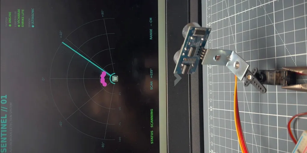
SENTINEL // 01
Ever built a robot with an FPGA? In this project, an FPGA and a MCU work together to make a moving surveillance system.
The Idea
SENTINEL // 01 turns an HC-SR04 ultrasonic sensor into a real-time radar. A servo sweeps the sensor across its surroundings, an FPGA and RP2040 handle the embedded side, and a Python application turns the measurements into the live radar display.
The system is built around the Vicharak Shrike Lite, which combines a Renesas ForgeFPGA with an RP2040 microcontroller. Rather than using the MCU for everything, the system splits the work between programmable logic and firmware: the FPGA handles the low-level hardware control, while the RP2040 handles the main system logic and communication with the PC. Python then sits at the top of the stack, turning the resulting measurements into a visual representation of the area being scanned.
The hardware is relatively simple, which makes this a practical project to experiment with, but the architecture introduces several useful embedded systems concepts at once: FPGA development, Verilog, MCU firmware, sensor interfacing, servo control, serial communication and real-time data visualisation.
What You’ll Need
The main development board, combining a Renesas ForgeFPGA with an RP2040 microcontroller.
View →The official documentation for getting started with the Shrike, including its FPGA + MCU architecture, toolchain and bitstream workflow.
Read →Used to connect the Shrike Lite, ultrasonic sensor and servo while prototyping.
Provides the configuration and programming workflow for the ForgeFPGA.
Open →Runs the desktop application that receives the measurements and renders the radar.
Open →Handles serial communication, measurement data and the real-time radar visualisation.
View →How It Works
The basic idea is straightforward: point an ultrasonic sensor in a particular direction, measure the distance to whatever is in front of it, then move the sensor and repeat. SENTINEL mounts the HC-SR04 to an MG90S servo, allowing the sensor to sweep through a range of angles. Each measurement therefore has two useful pieces of information: the distance detected by the sensor and the position of the servo when that measurement was taken.
HC-SR04 → FPGA → RP2040 → Serial → Python → Radar
The embedded hardware sits between the physical sensing system and the computer. The Renesas ForgeFPGA provides the low-level hardware-control layer, while the RP2040 handles the main system logic and communicates with the PC. On the computer, Python receives the incoming measurements and uses the scan position and distance to determine where each reading should appear on the radar.
This means the radar isn’t simply a graph of sensor readings. The servo provides the angular information while the ultrasonic sensor provides the distance information, allowing the Python application to reconstruct a simple two-dimensional representation of the area being scanned.
Building the FPGA side
The FPGA is used for the low-level hardware-control side of SENTINEL. The design is written in Verilog, with Go Configure Software Hub (GCSH) providing the main development and configuration workflow for the ForgeFPGA.
The development process also involves configuring the FPGA’s physical I/O so that the signals defined by the design are connected to the appropriate pins on the Shrike Lite. Once the design and I/O configuration are complete, the FPGA design is compiled into a bitstream. A bitstream is the configuration data that defines the programmable hardware implemented inside the FPGA.
The resulting configuration is then programmed onto the Shrike Lite using its LittleFS-based programming workflow.
This is one of the key differences between the FPGA side of the project and the RP2040 side. The FPGA isn’t being treated simply as another processor running a conventional program. The Verilog design defines hardware behaviour that is compiled into the programmable logic itself, providing the low-level hardware layer used by the rest of the system.
The RP2040 and embedded logic
The RP2040 provides the MCU layer above the FPGA. Its firmware is developed using the Arduino IDE, giving the system a conventional embedded software environment for handling the main system logic and communicating with the PC.
The important architectural decision here is the division of responsibility. The FPGA handles the low-level hardware-control layer, while the RP2040 handles the higher-level embedded behaviour and communication. This allows the two processing environments to work together rather than trying to make one device responsible for the entire system.
The RP2040 also provides the serial connection to the PC. Once the embedded system has the measurement data, the MCU sends it across that connection so that the Python application can process and visualise it.
Turning sensor data into a radar
The final layer of SENTINEL runs on the PC and is written in Python. The application uses PySerial to communicate with the RP2040, NumPy to work with the incoming measurement data and Matplotlib to generate the radar interface.
The key to creating the radar is combining the two dimensions of each measurement. The servo position tells the application where the sensor was pointing, while the HC-SR04 tells it how far away the detected object was. Python can use those values to place each measurement at the appropriate position on the radar.
As the servo continues to sweep, new measurements arrive over the serial connection and the display updates in real time. Instead of looking at a stream of numbers in a serial monitor, you get a visual representation of what the sensor is detecting.
Keeping this layer on the PC also makes the architecture much simpler. The embedded system doesn’t need to generate the graphical interface itself. Its job is to collect and communicate the data, while Python handles the more computationally and visually demanding part of the application.
Putting the whole system together
When SENTINEL is running, the process forms a continuous pipeline from the physical environment to the radar display. The MG90S moves the HC-SR04 through the scan range, the sensor produces distance measurements and the embedded hardware handles the control and system logic. The RP2040 then communicates the resulting data to the PC over serial.
PySerial receives that data in Python, where the scan position and distance measurement can be processed using NumPy. Matplotlib then uses those values to update the radar display, creating the real-time visual effect shown in the project.
The result is a relatively small system that crosses several layers of engineering. There is physical sensing and motion, programmable FPGA hardware, MCU firmware, serial communication and a desktop application, all working together as one pipeline.
This is also where the FPGA + MCU architecture becomes particularly interesting. The FPGA and RP2040 aren’t simply two different ways of doing the same thing. They provide different environments for different parts of the system, allowing low-level hardware behaviour and higher-level embedded logic to coexist.
Take it further
SENTINEL // 01 is designed as a starting point. Once the basic radar is working, there are plenty of ways to turn it into something considerably more advanced.
Make it wireless. Replace the wired PC connection with a wireless link and move the radar interface away from the physical sensing hardware.
Track objects. Instead of simply displaying individual measurements, process successive scans to identify objects and track their movement.
Build a mobile version. Put the sensing system onto a wheeled platform and use the radar data for obstacle detection or autonomous navigation.
Improve the sensing. Experiment with different sensors, wider scan ranges, different servo speeds or multiple sensors to build a more detailed representation of the environment.
Push more into the FPGA. Move additional low-level processing into programmable logic and experiment with how much of the sensing pipeline can be handled in hardware rather than firmware.
Build a better interface. Matplotlib is enough to create the radar, but you could replace it with a custom desktop or web-based interface and add features such as persistent measurements, object tracking, history or mapping.
The same FPGA + MCU + software architecture can therefore become the foundation for something much larger than the original ultrasonic radar.
Side Note
If you’re new to the Vicharak Shrike Lite, Vicharak also provides a range of examples and tutorials on GitHub that you can follow along with to get familiar with the board and its capabilities. These are a useful starting point before building your own projects, particularly if you’re new to working with the Shrike Lite’s FPGA and RP2040 architecture.